Synchronous Sampling
The first approach to be discussed is synchronous sampling of vibrations. Synchronous sampling is achieved by sampling vibrations at a sampling rate related directly to the rotational speed of the shaft. This enables the conversion of non-stationary vibrations into stationary vibrations, at which point conventional analysis techniques can be applied to extract useful diagnostic information about the signals frequency content. Two basic methods have been developed to enable this conversion. Adaptive Data Resampling (Tachometer) Angular Sampling (Optical Encoders)
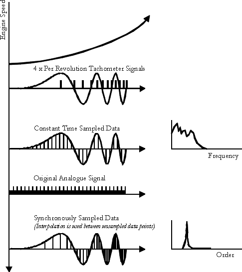
Adaptive Data ResamplingThe origins of angle data resampling lie in its predecessor, phase locked loop (PLL) analysis. Phase locked loop analysis uses a once per revolution tachometer signal, which was used to determine the rotational speed of the shaft, thus allowing vibrations to be analysed in terms of their shaft orders, and synchronous averaging to be employed. However the practicality of using a PLL is limited, as this approach is only applicable to slowly variable speed machinery. In order to overcome this limitation, angle data resampling or digital resampling [McFA86] was employed.Angle data resampling involves measurement of the rotational speed of the shaft, derived from a tachometer signal which is triggered at a fixed number of times per shaft revolution. Due to problems related to the resolution of the tachometer signal, the trigger rate of the tachometer is usually much lower than the fixed sampling rate. Because of this, the instantaneous angular position and speed at each data sample location is not accurately known [TAN89]. In order to obtain more accurate information about the location and angular speed of the shaft, various interpolation schemes have been trialed, ranging from the simple linear case to higher order polynomial interpolation. This enables intermediate angular speeds and positions to be calculated, providing the basis for resampling the data at constant angular intervals. Figure 14 shows conceptually how angle data resampling can be used to analyse vibrations from an engine during start up. Once the signal has been transformed into its angle domain, the FFT can be applied to analyse the order spectrum of the vibrations.

Angular Sampling (Optical Encoders)The problem with angle data
resampling is that for machines which exhibit rapidly fluctuating
speeds, accurate tracking of the shaft's instantaneous speed cannot
be achieved and a modest amount of spectral smearing may occur.
This problem can be alleviated by sampling vibrations at constant
angular intervals through the use of an optical encoder. Instead
of initially sampling the vibration signal at constant time intervals,
and then converting this signal into the angle domain by interpolating
between tachometer pulses to obtain the new sample times, the
digital sampling is carried out directly at equal angular intervals.
Current optical encoders enable the measurement of in excess of
9000 pulses per revolution, which can then be used to trigger
sampling. Although this method offers obvious benefits over angle
data resampling, it can only be applied where it is possible to
attach an optical encoder to the end of the respective shaft.